How to Position Solar Cameras for Maximum WiFi Range and Motion Detection
The 9-Foot, 15-Degree Rule governs optimal installation: Mount your solar camera 7 to 9 feet above ground, tilted 15 to 20 degrees downward, and oriented so targets walk laterally across the field of view. Always connect to a 2.4GHz WiFi network, maintaining a signal RSSI value stronger than -65 dBm in your mobile app before drilling mounting holes.
Essential Placement Guidelines
- Signal Baseline: Maintain an app RSSI reading between -30 dBm and -65 dBm. Signal drops below -75 dBm cause severe live-view buffering and missed event recordings.
- Network Frequency: Connect exclusively to 2.4GHz WiFi. Its 12-centimeter wavelength penetrates exterior walls up to 150 feet, whereas 5GHz signals attenuate within 30 to 40 feet outdoors.
- Target Trajectory: Passive Infrared (PIR) sensors detect thermal changes 5 times faster when targets walk side-to-side across the lens rather than moving head-on toward the camera.
- Mounting Height: The 7 to 9 foot mounting window balances PIR heat detection up to 30 feet with physical defense against vandal tampering.
- Solar Alignment: Position the solar panel facing True South (or Southwest in North America) tilted at 30 to 45 degrees to ensure 3+ hours of direct daily sunlight.
Spatial & Signal Specification Blueprint
Photo by yanping ma on Pexels
| Parameter | Target Value / Range | Critical Threshold | Impact on System Performance |
| --- | --- | --- | --- |
| App WiFi Signal (RSSI) | -30 dBm to -65 dBm | -76 dBm or lower | Below threshold causes 10+ second video latency, offline app alerts, and failed cloud backups. |
| Mounting Height | 7.0 ft to 9.0 ft | > 10.0 ft or < 6.0 ft | Exceeding 10 ft causes PIR heat signals to pass beneath the target; under 6 ft exposes camera to tampering. |
| Downward Camera Tilt | 15° to 20° angle | 0° (Horizon level) | Flat horizon alignment oversaturates sky lighting and cuts PIR ground sensitivity by 40%. |
| PIR Motion Radius | 15 ft to 30 ft | > 35 ft | Maximum detection distance for human-sized thermal signatures across a 120° detection arc. |
| Solar Panel Tilt Angle | 30° to 45° (South-facing) | < 15° flat mount | Sub-optimal tilt reduces photo-voltaic efficiency by up to 35% and allows dust accumulation. |
Reference these exact engineering parameters when testing hardware placement on your residential or commercial property.
Optimal Solar PTZ Camera Mounting & Motion Geometry
This schematic illustrates the spatial relationships between mounting height, downward lens pitch, solar exposure, and optimal target travel pathing.
Signal & Detection Troubleshooting Matrix
| Scenario / Symptom | Primary Root Cause | App Diagnostic Reading | Step-by-Step Resolution |
| --- | --- | --- | --- |
| Live video buffers or disconnects constantly | Signal attenuation through dense masonry or double-pane Low-E glass walls. | RSSI between -76 dBm and -90 dBm | Relocate WiFi router closer to exterior wall or install an outdoor 2.4GHz range extender within 20 feet of the camera. |
| Camera fails to trigger when subjects walk directly to the door | Head-on motion path prevents PIR thermal zone boundary crossing. | PIR Sensitivity set to Low / Medium | Re-angle camera 20 degrees sideways so subjects cut across the 120° PIR arc laterally; elevate PIR sensitivity to High. |
| Excessive false alerts during hot afternoon hours | Thermal heat reflections from HVAC exhausts, concrete driveways, or swaying sunlit foliage. | Normal RSSI; frequent false event clips | Adjust motion mask zones in the mobile app to exclude heat-radiating surfaces and set PIR human-filtering mode. |
| Camera goes offline after 3 consecutive overcast days | Solar panel shaded by roof overhang or facing North/East, preventing battery float charging. | Battery percentage < 10% | Unmount solar panel and relocate using extension cable to a South-facing fascia board receiving 3+ hours of direct sunlight. |
Diagnose common field anomalies by correlating app readings with physical environmental triggers.
Pro Tip: Live RSSI Verification Prior to Drilling
Never drill pilot holes based on visual intuition alone. Before mounting your camera bracket, power on the unit, pair it to your 2.4GHz network, and physically hold the camera against the exterior surface at your intended mounting height. Open the device settings in your app and wait 60 seconds for the RSSI reading to stabilize. If the signal reads weaker than -65 dBm (e.g., -72 dBm), shift the camera 3 to 5 feet horizontally along the wall. Moving away from internal aluminum studs, electrical panels, or copper plumbing can immediately recover 8 to 12 dBm of signal strength without adding hardware.
Pre-Installation Verification Plan
Your decision: Determine your camera's exact mounting location based on lateral pathing and signal testing.
Do this next: Hold the camera at the intended position, open the management app, and confirm an RSSI value stronger than -65 dBm before drilling.
- Read next: Fix Outdoor Security Camera WiFi Disconnections and Offline Alerts
- Read next: Solar Security Camera Mounting Options: Vinyl Siding, Brick, and Gutters
Equip your home with the Outdoor Solar Security Camera (Pack) featuring PTZ coverage and long-range 2.4GHz WiFi.
Follow these steps to confirm signal and coverage before permanent physical fastening.
Positioning Selection Framework
Select mounting locations based on building material conductivity and lateral motion paths rather than simple line-of-sight distance from the router.
Best choice for
- Direct Wall Mounting at 8-9 Feet — Offers minimal signal attenuation (1-3 dBm loss) and ideal horizontal PIR coverage across primary entryway paths.
- Corner Mount or Exterior Soffit Alignment — Bypasses dense exterior masonry walls by routing signal through adjacent window frames or wood soffits.
- Dedicated Outdoor 2.4GHz Access Point — Overcomes extreme distances and metallic barriers, restoring weak RSSI (-78 dBm) to optimal range (-52 dBm).
- Do not mount directly onto sheet metal siding or aluminum fascia without rubber isolation spacers, as metal surfaces create RF multi-path interference.
- Do not point PIR sensors directly down narrow driveways toward approaching vehicular traffic, as head-on motion delays trigger times by 2 to 4 seconds.
- Adjustable Pole Bracket Mount — Allows placement 10-15 feet away from the building envelope to gain direct line-of-sight to both the WiFi router and Southern sunlight.
Recommended Outdoor Surveillance Hardware
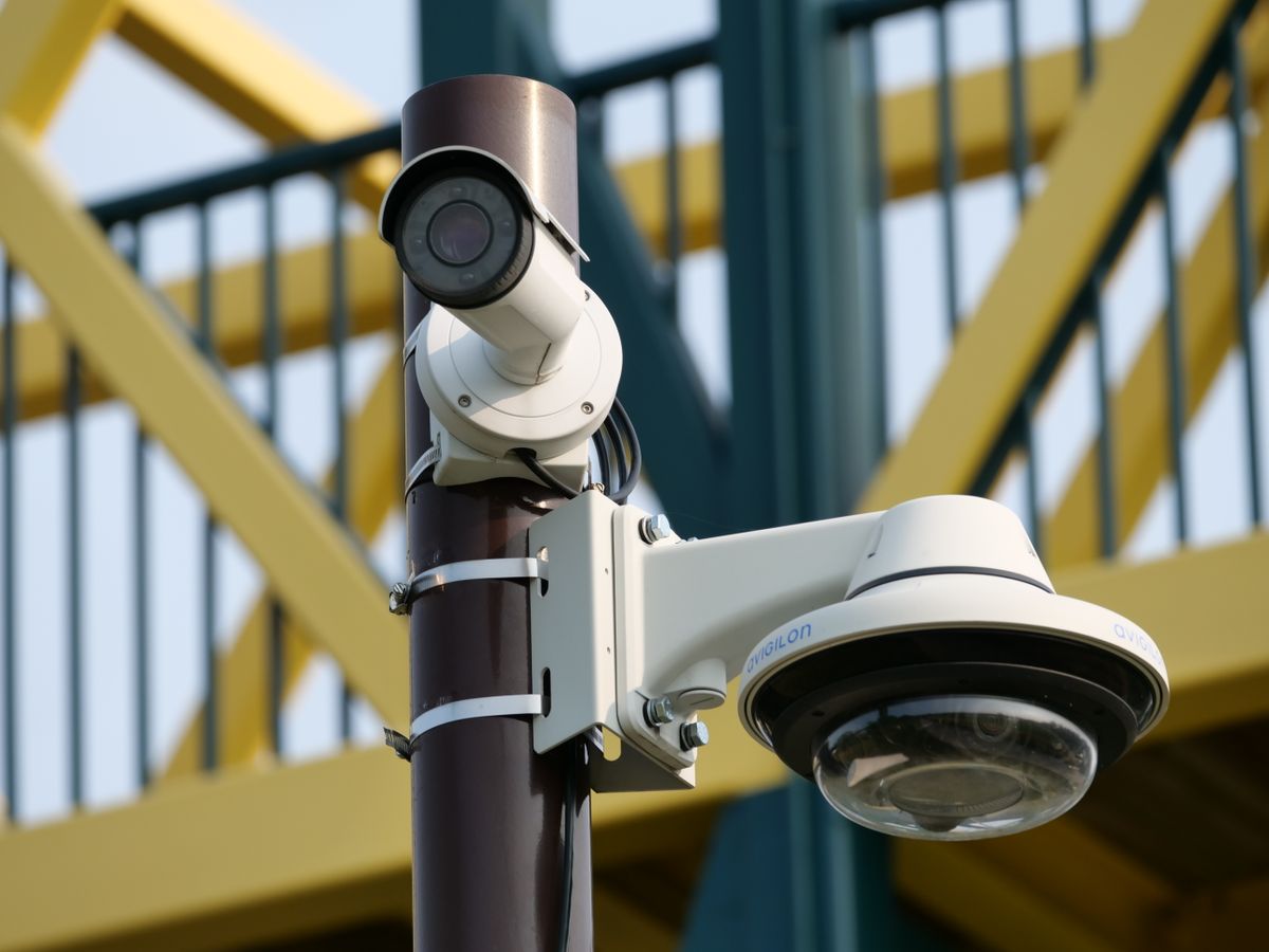
Photo by Giant Asparagus on Pexels
When positioning outdoor wireless security, hardware capability dictates operational success. The Outdoor Solar Security Camera (Pack) is engineered specifically to eliminate blind spots and overcome exterior wall signal loss.
Key features include:
- 355° Pan & 90° Tilt (PTZ): Remotely adjust your viewing angle via app to fine-tune coverage without climbing ladders.
- High-Gain 2.4GHz Wireless Antenna: Engineered for high receiver sensitivity through brick and siding.
- Color Night Vision & Two-Way Audio: High-output spotlights illuminate targets up to 30 feet away, delivering full-color video in total darkness while enabling instant real-time talkback.
- Dual Storage Options: Encrypted local microSD support alongside secure cloud backup safeguards your critical incident footage.
1. The Physics of Outdoor 2.4GHz WiFi Propagation
Unreliable video feeds are rarely caused by a camera defect; they are almost always the result of RF signal degradation across exterior building envelopes. WiFi routers broadcast signals in spherical waves. When a 2.4GHz wave (approx. 12 cm wavelength) strikes an exterior wall, part of the energy reflects back, while the rest passes through, suffering signal loss measured in decibels relative to milliwatts (dBm).Signal strength in mobile management applications is expressed as a negative number. An RSSI of -45 dBm represents an exceptionally strong connection, while -80 dBm indicates a marginal connection on the verge of total drop-out. Every 3 dBm drop represents a 50% loss in RF signal power. Passing through standard 4-inch brick veneer strips away 10 to 12 dBm—a reduction of over 75% of available signal power in a single barrier.
To ensure consistent 1080p or 2K video streaming, your camera requires an RSSI stronger than -65 dBm. This leaves sufficient signal margin to absorb atmospheric interference, rain fade, and ambient RF noise from neighboring networks.
2. PIR Motion Geometry: Why Lateral Motion Triggers Faster
Passive Infrared (PIR) sensors do not 'see' color or movement in the traditional optical sense. Instead, they monitor ambient infrared radiation across a grid of alternating thermal detection zones. The sensor triggers an alert when a warm body (human or vehicle) disrupts the thermal baseline by moving from one detection zone into another.- Head-On Trajectory (Poor): When a person walks directly toward the camera lens, their thermal profile occupies the same central detection zone for several seconds. The PIR sensor detects only a gradual increase in image size, delaying alert triggering by 2 to 4 seconds—often missing the event entirely.
- Lateral Cross-Field Trajectory (Optimal): When a person walks horizontally across the camera's field of view, their body cuts across multiple alternating thermal zones in milliseconds. This rapid differential triggers the camera instantly, capturing the subject in the center of the frame.
WiFi Signal Attenuation by Exterior Building Material
| Building Material Scenario | 2.4GHz Signal Loss (dBm) | Effective Range Reduction | Mitigation Strategy |
| --- | --- | --- | --- |
| Standard Wood Frame + Vinyl Siding | 2 dBm to 4 dBm | 10% to 15% range reduction | Standard router placement usually sufficient within 75 feet. |
| Double-Pane Low-E Glass Windows | 4 dBm to 8 dBm | 20% to 35% range reduction | Position camera away from window frames coated with metallic thermal films. |
| Red Brick Veneer / Cavity Wall | 10 dBm to 14 dBm | 50% to 65% range reduction | Mount camera near wood soffits or install an outdoor mesh node. |
| Poured Concrete / Stucco over Wire Lath | 15 dBm to 20 dBm | 70% to 85% range reduction | Wire lath acts as a Faraday cage; requires an external wireless access point. |
| Corrugated Metal Siding / Steel Doors | 20 dBm to 28 dBm | 85% to 95% range reduction | Avoid direct mounting on metal surfaces; use non-metallic standoff spacers. |
Understand how common exterior wall materials degrade 2.4GHz wireless signals from your indoor router.
5 Critical Mounting Errors That Degrade Signal & Sensing
Avoid these five frequent installation errors to maintain 24/7 reliability:
Related Placement & Technical Guides
- Solar Panel Camera Positioning FAQ: Direct Sunlight, Shade, and Seasonal Adjustments
- Can an Outdoor Solar Security Camera work without WiFi?
- Deploying Outdoor Solar Security Camera Systems Without Wifi
Frequently Asked Questions
Answers to critical technical questions regarding RSSI thresholds, wireless frequencies, and sensor obstacles.
Final Action Plan
Your decision: Finalize your camera angle and mount position based on RSSI strength and lateral PIR coverage.
Do this next: Mount the Outdoor Solar Security Camera Pack at 9 feet with a 15-degree downward tilt and verify RSSI > -65 dBm.
- Read next: Fix Outdoor Security Camera WiFi Disconnections and Offline Alerts
Outdoor Solar Security Camera (Pack)
Complete your outdoor surveillance layout with these expert execution steps.
Cover photo by tommy picone on Pexels.